Understanding GPIO using the Raspberry Pi Pico

It’s standard for platforms like the Raspberry Pi Pico (microcontrollers in general) to have a set of pins called GPIO. In the diagram above you can see that the Pico has 40 total pins, and 26 of them are classified as GPIO. If you look purely at the numbers the pins title GP go from 0 to 28, so I initially assumed there were 29 pins available. But for some reason, there are no pins 23, 24, or 25. I couldn’t find anything quickly online about why they are missing.
Turns out GP25 controls the onboard LED, but I don’t know what 23 or 24 do.
GPIO = General Purpose Input/Output
Because the microcontroller is meant to be configurable by the end user, its pins need to be general-purpose to provide more flexibility to the application under development. If you’re new to controllers, this whole concept of pins might be a bit alien so I’ll quickly cover a few different types.

Sensors and other field devices allow a controller to know the ‘state’ of a process, and control devices based on that state.
Discrete IO
When passing information between devices often it’s only necessary to exchange “yes” and “no”. Fortunately, with discrete IO this can be done with the presence or absence of voltage. The controller or a field device can toggle voltage states, and these voltage level changes create context in the larger system. This context is built by the designer and should represent reality just well enough for the system to operate reliably.
Let’s look at some examples.
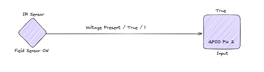
This IR Sensor Field IO device sends a true signal back to GPIO Pin 2 (GP2 or pin 4 on on the pico)
Inputs + Sensors
A motion sensor (let’s say Infrared) in the field detects movement. If the goal is to turn on a light when motion is detected, the only thing the sensor needs to send back to its controller is “true”, or a boolean.
Let’s also say the motion sensor is hooked into a GPIO pin on the controller that is configured to be an Input. The sensor sends true (voltage is present) to that pin, and now the controller has the information to make a decision on what to do when motion occurs.

An output pin turned off (above) and then turned on (below) supplying power to a light.
Outputs + Lights
Now that the controller has context that motion has happened in the field, it can be set up to illuminate that area so that people walking around can see what they are doing.
The controller itself can now have a GPIO pin that sends a discrete signal to a light in the field.
This is mostly how a motion-detecting exterior light works! So with only two GPIO pins, you can build your own exterior lighting control system. The Raspberry Pico is overkill for a system like this, but it’s cheap enough that doing it wouldn’t be terribly cash wasteful.

Pulse Width modulation is technically Discrete IO (on or off); but hyper fast
Pulse Width Modulation (PWM)
Pulse width modulation is a way to control a percentage of a time slice that a device receives power. Another way of looking at is it using a wave function to produce a perceived magnitude.
Let’s use an LED lamp as an example
If you set up the PWM so that over a period of 1 second, a LED lamp receives power for .5s, you might try to turn the device on for .5s, and then off for .5s.
This would work! But you’d get a flashing lamp, alternating on and off 1x per second.
What if you want to dim the lamp though? This is possible through PWM. You can flicker the on-off state with PWM so quickly that the human eye can no longer perceive that the light is ever turning off, and instead the light will appear dimmer because the light cannot reach its maximum luminosity nor reach 0% luminosity because the power is changing states too quickly.

The LED is kept in a state of less than 100% luminosity but more than 0% Luminosity creating the ‘dimmed’ effect.

Controllers can send data structures to subordinate devices or other controllers.
Communications Configurations
Even though Discrete IO is technically communication, the interpretation of discrete signals is left totally to the person building the application.
This is not true for communications protocols like I2C, SPI, and UART.
Communications protocols are standards that define a ‘secret handshake’ between devices. Devices that understand the secret handshake are capable of exchanging streams of data rather than receiving and sending true and false signals.
Using these handshakes, a device can confirm it’s identity, give detailed information, and receive detailed information in less than 1 second. I won’t cover any real detail about these protocols, but I can say that learning to use them grant the application developer more power over a distributed system.
GPIO & Comms Protocols
The pins of the Raspberry Pico can be set up to function as comms pins. The diagram at the top of the page covers which pins can be used for which protocols. The Pico Platform can’t handle every protocol on every pin because there are specific circuitry and hardware requirements per protocol. Only certain pins have the needed components in place on the board to handle these requirements.
Other Pins
Some pins on the board are not GPIO and I won’t cover them here as this post has already ended up longer than I wanted. But It’s definitely worth knowing that not every pin on the board can function as a GPIO pin.
Conclusion
The GPIO pins of a Raspberry Pico (or any controller) are meant to give interfacing capability to other field devices, controllers, or even computers. The controller is able to better understand it’s operational mode ‘state’ through these pins, and is also able to send control signals to devices or communications data to devices based on process state change.
This has been a fun post to make, and I’m leveling up with Excalidraw by making these diagrams. Next time I think I’ll be covering using the Pico & Rust to communicate with a very tiny OLED LCD screen.